The Quadcopter Application
The quad application is the brains of the quadcopter.
It must perform the following:
-
Receive inputs and compute motor outputs to maintain stable flight
- accomplished through the control algorithm
-
Parse and send message packets in order to communicate with the
ground station
- Respond to commands sent by ground station
- Send ground station logs
Controller Network (Control algorithm)
First read the documentation for the computation graph library to understand how the graph computes functions from a directed graph.
To visualize the default control network, from the quad/ folder, run make diagram with graphviz installed, and an image of the control network will show up as network.png in the src/gen_diagram folder. To see the autonomous controller, you can change the call at the bottom of control_algorithm_init from connect_manual() to connect_autonomous() before running make diagram. Just be sure to change it back to connect_manual() before the final build. Below is a simplified version of the autonomous controller that shows the control network for autonomous flight using VRPN data. (Unused blocks relating to manual flight and optical flow have been removed, as well as Ts_IMU and Ts_VRPN, which are blocks that keep track of the sampling period)
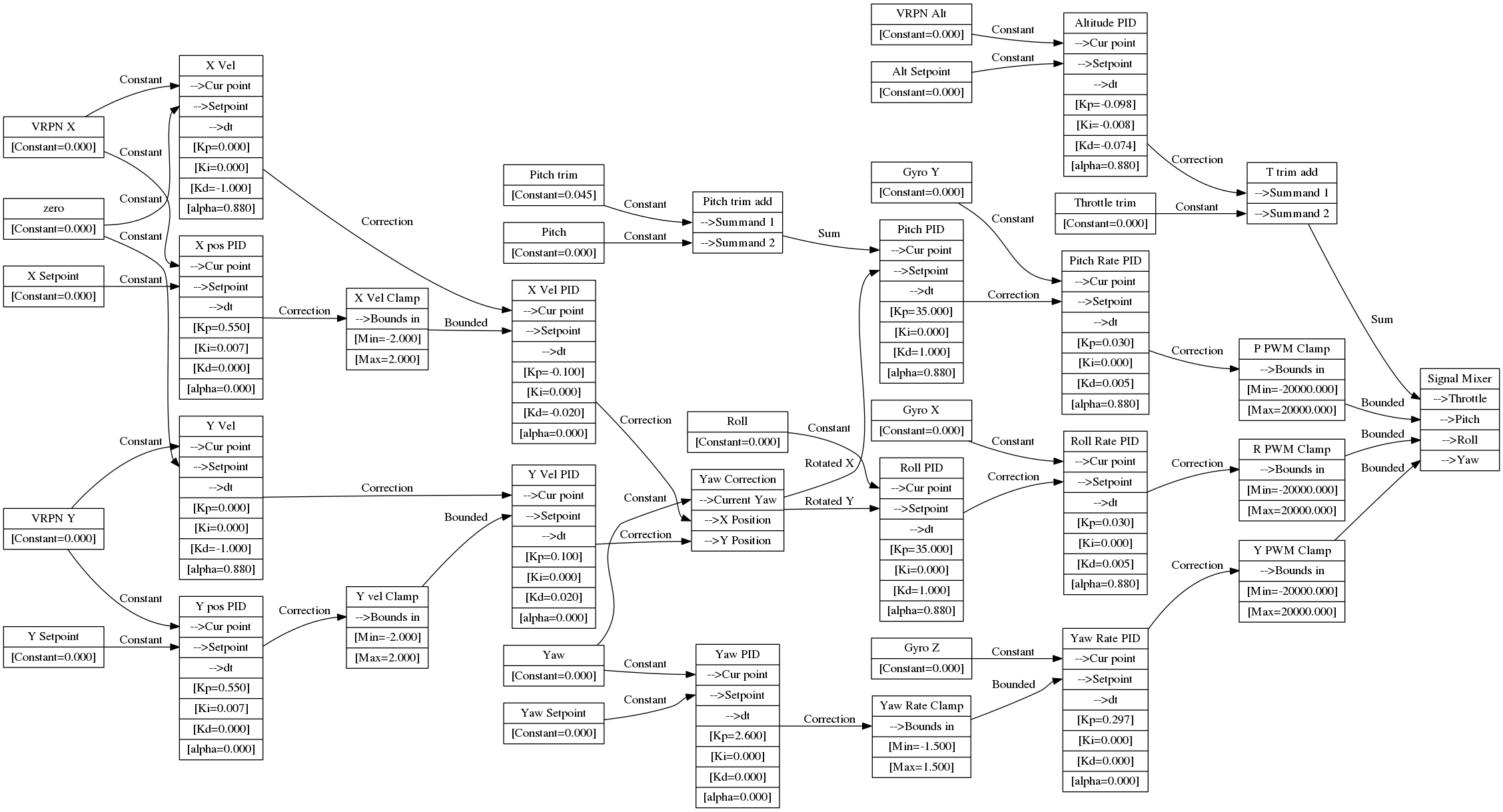
One potential confusing point to take note of is the difference between "(X/Y) Vel PID" and "(X/Y) Vel" blocks. "(X/Y) Vel" is just a PID controller that has Kd=-1, which results in calculating the derivative of position to provide velocity. For clarity, it would be a good idea to create an actual differentiation block.
- Note our use of derivative on value, not error
What about the Brauns?
We said that the application is the brains, and it is just that. It computes outputs from inputs, but it has no idea where those inputs come from, or where its outputs should go.
Specifically, the application has 12 unimplemented interfaces, defined in
hw_iface.h. This design allows us to run the quad application
on whatever hardware we want, we just have to implement the interfaces.
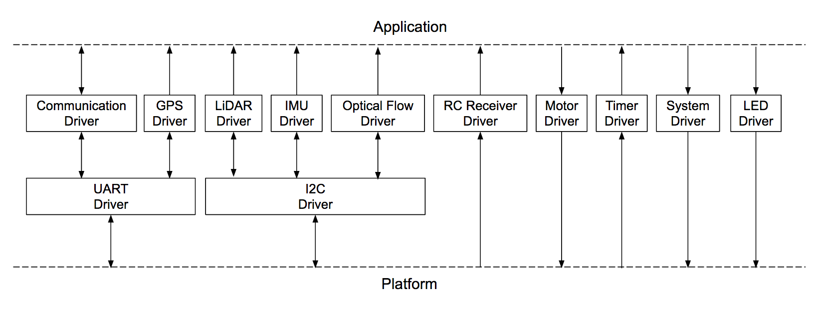
We have 2 primary platforms on which we run the quad application:
- Used to actually fly the quad
- Used in automated testing and to ease ground station development
Optical Flow
The current (end of may17-16) state of optical flow is that it can be used autonomously be uncommenting all four defines at the top of control_algorithm.c. It is relatively stable, but drifts over time. Setpoints do work, but yaw needs fixing (See issue #23 (closed)).
We are using the PX4Flow optical flow sensor. Read more about it here and here. The source code for the firmware can be found on Github.
Improvements to be made
- Compensate for rotation of sensor. The PX4Flow has the ability to enable gyroscope compensation (The firmware must be re-flashed for changes to persist), but when we tried it, the output was much worse. We then implemented our own gyroscope correction, using the complementary-filtered pitch and roll, since they will not drift over time (Using raw gyro would result in drift in position because of gyrosope angle drift). The actual data didn't look much worse, and for large, slow movements, the gyroscope compensation seemed to help prevent incorrect measurements, but it always made flight worse, probably beause of high-frequency noise. Using the complementary filter might be the cause, since it essentially high-passes the accelerometer readings, which are very noisy. We then also tried putting a low-pass filter on phi_dot and theta_dot, but it didn't help flight. Possibly the delay added by the filter caused the correction to not align with the actual movements.
- Possibly just switch to a better optical flow sensor. This one has not had any developments in the past couple years, is hard to buy, and is poorly documented. The best documentation is to actually look in the source code, because we have found multiple discrepancies in the documentation.