Computation Graph
A computation graph is a way to organize a large function into smaller, reusable functions, and easily visualize how data flows from one step of calculation to another. We chose to implement the control algorithm in this manner because as the complexity of the controller grew (deeper PID nesting, more filtering, etc.), it became very difficult to understand exactly how the sensor data was being processed and used. Our final design is partially inspired by Simulink, in an effort to draw parallels between the actual implementation of a controller and how they are often designed by control engineers.
Example
To help understand the basics of the computation graph, we will walk through a simple example. Below is a possibly graph configuration, along with a representative Simulink diagram. Each node represents a computation step which takes in inputs, and produces outputs. Each node also potentially has configuration parameters.
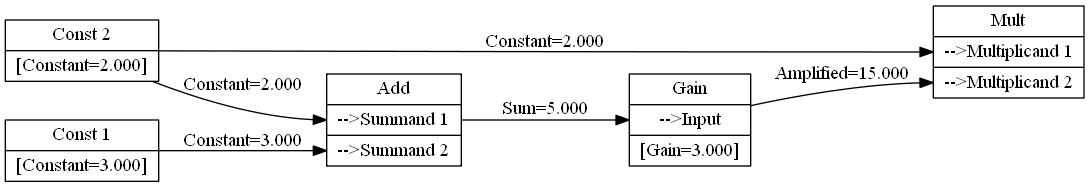
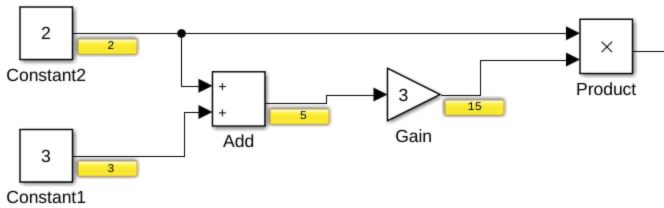
In this example, there are four different types of nodes:
- Constant
- Addition
- Gain
- Multiplication
Constant
A constant block, as defined in node_constant.c and node_constant.h has:
- 0 Inputs
- 1 Output
- CONST_VAL
- 1 Parameter
- CONST_SET
When its computation is executed, it simply sets the output to be the value of the parameter CONST_SET.
Addition
An addition block is defined in node_add.c and node_add.h has
- 2 Inputs
- ADD_SUMMAND1
- ADD_SUMMAND2
- 1 Output
- ADD_SUM
- 0 Parameters
During its computation step, it calculates the difference between the values passed into ADD_SUMMAND1 and ADD_SUMMAND1, putting the result in ADD_SUM.
Gain, Multiplication
Both of these blocks have implementations (node_gain, node_mult). They are both simple blocks that perform a single operation.
Storing State
The blocks introduced above are purely functional: Every input combination maps to a single output combination, regardless of past inputs. To implement controllers and filters, we need something more powerful --- Introducing block state.
A block implementation can define a custom struct for storing any sort of data it would like. Each new instantiation of a block allocates memory for the struct, and the block execution function gets a void* passed into it, which the execution function is responsible for casting and using.
A simple stateful block
To help explain these ideas, we'll go through a simple block that uses state: An accumulator node (node_accumulator.c and node_accumulator.h).
This block performs the following operation: Every time its execute function is called, it outputs the sum of its previous output with the current input. i.e., it computes \sum_{t=1}^{T}{x_t}.
Clearly, our state needs to store the total summation so far. In the implementation, you will see that the accum_state struct has a single field which contains a double representing the accumulated value. The accumulate block also contains a reset function, which sets the accumulated value to 0.
You may wonder why a node_integrator block exists in addition to the accumulator block. The integrator block computes a proper integral, taking into account the time difference between calls, dt, and is used for the optical flow calculations. The accumualtor block is actually only used for automated testing.
Initializing State
If a block has state, we probably want a way to initialize the state in some way. If the initialization were to only occur once, we might have left it up to the block implementation to keep a flag in the state struct representing whether it has been initialized. But because blocks can be disconnected and reconnected during runtime (e.g. switching from manual to autonomous flight), the initialization may need to run multiple times, so we allow a block definition to provide a function that will be called upon block initialization (reset field in grah_node_type struct).
Reset Propagation
When a block is connected to the graph, we want it to be reset. Because it is part of a chain of computations, we usually want its ancestors to be reset also. Consider the graph below. When D is connected, both B and A will have their reset functions called.
