-
 Austin Rohlfing authoredAustin Rohlfing authored
Simulink Model
This documentation is about the Simulink model of the quadcopter found in controls/model/.
Specifically, the description and images are from the file
Quadcopter_Model.slx.
1 Top Level
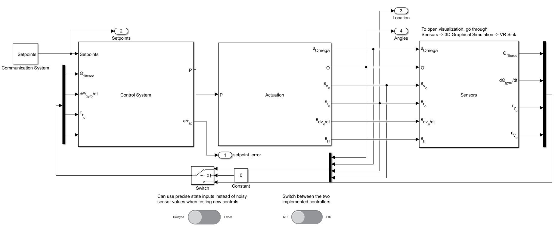
At the top level Simulink model (shown above), there are three primary components:
- Control System
- Actuation
- Sensors
There is also the input of setpoints, a vector of the four setpoint values: x, y, z, and yaw.
1.1 Variables
The variables used at the top level of the model are as follows:
-
\Theta_{\text{filtered}}- The current vector of roll, pitch, and yaw -
\frac{d\Theta_{\text{gyro}}}{dt}- Time derivative of\Theta, as gvien by the gyro -
^Er_0- Position of the quad with respect to the static reference frame -
P- Vector of PWM percentages sent to the ESCs -
^B\Omega- Vector of angular velocities aroundb_x, b_y, b_z -
\Theta- Roll, pitch, and yaw in the inertal reference frame -
\frac{d^Bv_0}{dt}- Time derivative of velocity in quadcopter reference frame -
^Bg- Gravity in quadcopter reference frame
The three components are further discussed in the sections below.
1.2 Switches
The top level also contains two toggle swtiches that change the operation of the simulation. The left switch toggles between using exact and noisy values for the controls. The switch that this toggle controls appears directly above it in the model, and its output is used for all but on of the Control System inputs. The right toggle switch changes the simulation from using the LQR controller to using the PID, or from PID to LQR. The components that this directly affects are all in the Control System block.
2 Control System
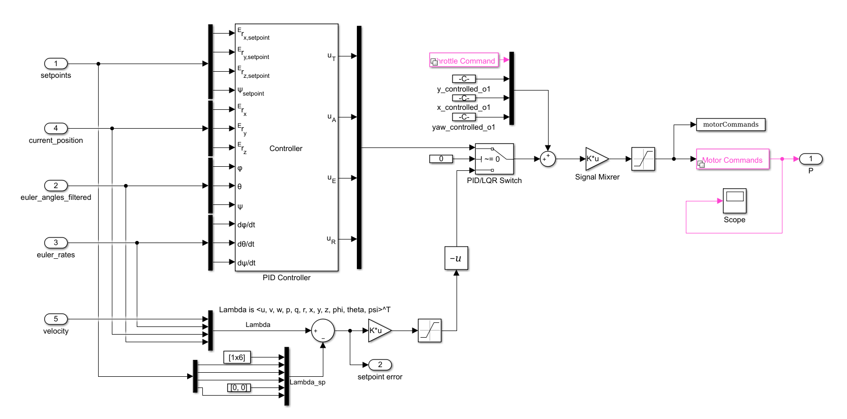
The three central components of the Control System are the two controllers and the Signal Mixer.
2.1 Variables
The variables used in the controls system not listed above are enumerated below:
-
u_T- Controller output for thrust -
u_A- Controller output for "ailerons", used to control roll -
u_E- Controller output for "elevators", used to control pitch -
u_R- Controller output for "rudder", used to control yaw
2.2 Controllers
There are two separate controllers implemented in this subsystem, a PID controller and an LQR controller.
2.2.1 PID Controller
This controller contains the actual PIDs for each element of the setpoint,
and outputs control values to the signal mixer. The inputs to the signal mixer are
values for thrust, aileron, throttle, and rudder. Inside the PID Controller block
are four sets of nested PIDS, one for each of the output commands. For example,
the u_A output is determined by state variables y, v, \phi, and, p
(i.e. lateral position, lateral velocity, roll, and roll rate).
2.2.2 LQR Controller
LQR is a state-feedback controller (currently without an observer) that generates
command outputs directly from the state estimation provided by the sensors.
The details of the controller and how it is designed can be found in the
LQR_Design.md documentation.
2.3 Equilibrium inputs
The result of either controller is added to the equilibrium input before being
passed to the signal mixer. Equilibrium for this system is when the quadcopter
is hovering, so u_T must be non-zero (all the other commands are zero, however).
This correction is required for the LQR controller to work. Though not strictly necessary
for the PID controller, not correcting for equilibrium input would initially respond
very slowly as the throttle PID loop accumulated its error integration.
2.4 Signal Mixer
Because the output of the controllers is in a style more fit for airplanes or helicopters
than a quadrotor, we need to convert the control result values to something meaningful
to control our flight with.
The Signal Mixer is simply a 4 \times 4 matrix that is multiplied by the vector
\begin{pmatrix}u_T & u_A & u_E & u_R\end{pmatrix}^\top to produce a vector
of PWM commands for the motor. As such, each row of the matrix corresponds to one
of the rotors, while each column corresponds to one of the elements of the input vector.
S = \left(\begin{array}{rrrr}
1 & -1 & -1 & -1\\
1 &  1 & -1 &  1\\
1 & -1 &  1 &  1\\
1 &  1 &  1 & -1
\end{array}\right)
For example, the fourth column is \begin{pmatrix}-1 & 1 & 1 & -1\end{pmatrix}^\top,
so when the controller commands a positive rudder (i.e. positive change in yaw),
the speed of rotors 1 and 4 decrease and 2 and 3 increase.
When comparing different research or implementations, be careful to compare signal mixing matrices. Everyone has their own scheme for number the rotors and orienting the quad, but the signal mixer should give enough information to determine the rotor configuration.
3 Actuation
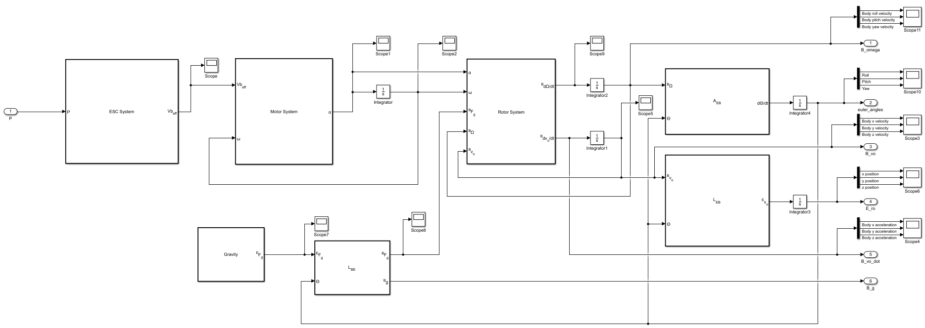
The Actuation component of the model takes the PWM percentages as inputs and simulates the motion of the quadcopter after being given a command from the control system.
3.1 Variables
The variables in Actuation that haven't previously been covered are below:
-
^EF_g, ^BF_g- Force of gravity on the quad, in inertial and body reference frames, respectively -
V_{b_\text{eff}}- Effective batter voltage, explained further in the ESC subsection -
\omega- Vector of angular speeds of the motors -
\alpha- Vector of angular accelerations of the motors -
L_{BE}- Matrix to transform a vector from the inertial reference frame to the quad's frame -
L_{EB}- The transpose (and thus inverse) ofL_{BE}; transforms from the quad's reference frame to the inertial frame -
A_{EB}- Matrix to transform a vector of angular velocities from the quad body reference frame to the derivative of the Euler angles
3.2 ESC System
The ESC System takes in the input vector of PWM percents, scales them between the max and min allowable duty cycles, and then calculates the effective battery voltage given to each motor (The motors are brushless, so effective voltage is the DC voltage that would need to be applied to a similar brushed motor to achieve the same output).
3.3 Motor System
Given the vector of effective voltages and a vector of current angular velocities for each motor, this block computes the angular acceleration for each.
3.4 Rotor System
The Rotor System first computes the total force and torque acting on the quadcopter body. The force consists of the thrust produced by the rotors as well as the downward force from gravity. The torque consists of components caused by in-plane drag, changes in rotor angular momentum, and thrusts at a distance from the center of mass. These values are then used to compute the outputs: the linear and angular accelerations in the quadcopter body frame of reference
3.5 Other Components
There are a number of smaller components in the Actuation model. There are several blocks that simply perform multiplication of the transformation matrices (covered in the Variables subsection) and a block that outputs a constant gravity vector. In addition to this, there are several integrators that accumulate linear and angular velocity and acceleration to accumulate current values for velocities and position/orientation.
4 Sensors
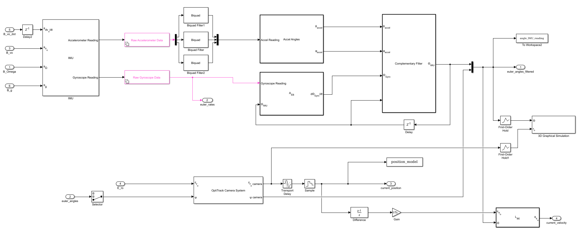
The Sensors component of the model performs no calculations (except for some basic trigonometry to convert gyroscope accelerometer values). All components of this function to simulate the actual system that the data would be sent through. These simulation components add noise to an input value (calculated in the Actuation phase), sample, quantize, and delay their readings. Without these, the Simulink model would only be good to prove math, and would not actually provide valuable insight into the physical system.
The 3D Graphical Simulation block can be opened to geive a simple visualization of the quad's flight.